
Track and Timing
This page describes standard track wiring and the computer timing system setup and configuration.
CARRACE uses a Clipsal 439/110 three point plug (two round pins with a flat earth pin). All members tracks are wired in a positive polarity, so when purchasing a hand controller such as those made by Professor Motor, please ensure that it too has positive polarity. There are a wide variety of hand controllers that are permitted including those manufactured by: Slot-it, MRRC and Professor Motor. The voltage for each class may be set by the track owner on the night but generally will be in the range of 10-12 volts.

All of the CARRACE tracks use positive polarity wiring, this means that it is the positive rail that the controller varies when the trigger is moved. Most controllers are electronic controllers, which are polarised, i.e., you must use a positive polarity controller on a positive polarity track.
Bill of Materials
These are the components you will need in order to wire up the power for your track. The links and prices given are mostly from Jaycar Electronics and are generally available in Canberra. These components can be purchased elsewhere, such as eBay, which will be cheaper, but will take longer to be shipped.
| Component | Quantity | Details | Approximate Cost |
|---|---|---|---|
| Controller Sockets (CARRACE standard) | 1 per lane | Clipsal 412/110 Single Socket Outlet | $35.50 ea |
| Direction Switch (optional) | 1 per lane | DPDT 6A 240VAC Heavy Duty Centre Off Standard Toggle Switch | $5.95 ea |
| Variable Power Supply | 1 |
$169.00 $79.00 | |
| Wire | 2-3m per lane |
$0.65 per metre $0.65 per metre |
Positive Track Wiring
This diagram shows the simplest track wiring that is possible, it will only have one direction of travel and no power cut capability.

Positive Track Wiring with Direction Switches
This diagram adds direction switches to the track wiring, allowing you to run your track in both directions.
Note the direction switches are between the controller sockets and the lanes.

Positive Track Wiring with Power Cut Relays
This diagram adds power cut relays to the track wiring, allowing the timing software to stop the cars. Your track will only have one direction of travel.
The optional wiring in this diagram will give the cars full brakes when the power is cut.

Positive Track Wiring with Direction Switches and Power Cut Relays
This diagram adds direction switches and power cut relays, allowing you to run your track in both directions, and allowing the timing software to stop the cars.
Note the direction switches are between the controller sockets and the lanes.
The optional wiring in this diagram will give the cars full brakes when the power is cut.

Bill of Materials
These are the components you will need in order to use Race Coordinator timing software with Arduino hardware. The links and prices given are from Jaycar Electronics and are generally available in Canberra. These components can be purchased elsewhere, such as eBay, which will be cheaper, but will take longer to be shipped.
| Component | Quantity | Details | Approximate Cost |
|---|---|---|---|
| 5v Power Supply | 1 | Use an old phone charger | $0.00 |
| 56Ω Resistor | 1 per lane | 56 Ohm 0.5 Watt Metal Film Resistors | $0.85 for a pack of 8 |
| Arduino | 1 | Duinotech UNO r3 Development Board | $29.95 |
| Arduino Prototype Shield | 1 | Duinotech Arduino UNO Prototyping Shield with Screw Terminals | $14.95 |
| Call Button | 1 - many | Small Black SPST N/O Momentary Action | $3.95 ea |
| Call Button Cable | 1-2m per call button | Light Duty Fig 8 Speaker Cable | $0.70 per metre |
| Lap Sensors | 1 per lane | Infrared Phototransistor | $1.75 ea |
| Light Bridge LEDs | 1 per lane | White 5mm LED 33000mcd Round Clear | $2.75 ea |
| Power Cut Relays (optional) | 1 | 4 Channel Relay Shield Module for Arduino | $14.30 |
| Sensor and Light Bridge Cable | 2-5m | Cat 5e Solid Core Network Cable | $1.20 per metre |
| Start Lights (optional) | 5 - 10 | WS2811 or compatible RGB LEDS | $12 for a pack of 10 |
Wiring it up
The below wiring diagrams shows a simplified view of how the timing system should be wired up if you are not using power cut relays.
Basic Arduino Timing System

Arduino Timing System with Power Cut Relays

Arduino Timing System with Start Lights

Notes
- The light bridge LEDs and lap sensors will be damaged if they are wired backwards, take note of which wire shold connect to which leg.
- The light bridge LEDs and lap sensor legs can be distinguished by their length.
- It is best to connect the 56Ω resistors directly to the light bridge LEDs.
- Do not get the light bridge LEDs and lap sensors mixed up, they look the same but function very differently.
- Using addressable LEDs for start lights is a complicated process, there are multiple options with different specs and different pin outs, it requires some knowledge of electronics to implement and is not for the faint-hearted.
- Addressable LEDs must be connected to pins A0 - A3 on the Arduino, this is hard coded in Race Coordinator.
- For start lights, use Race State 1 - 5 in expert track setup, the order will depend on how you connect the LEDs to each other.
- Where the colored lines cross other lines, they are not to be connected together.
- Where the colored lines touch with a dot, they are to be connected together
- If you would like multiple call buttons, they are wired in parallel to the call button on the diagram, ie the black wire connects to one pin and the brown wire connects to the other.
- You do not have to use the specific coloured wires shown in the diagram, the colours shown are just an example.
CARRACE uses Race Coordinator for
computer timing. Race Coordinator is a
free alternative slot car lap counting software package for the PC
. It is highly featured
and does everything we need for computer timing.
If you like Race Coordinator and use it regularly, please consider donating to Dave, the Race Coordinator developer, or supporting his nominated charity. Click here for more information
Race Coordinator can be downloaded here.
To configure Race Coordinator to use the Arduino timing system:
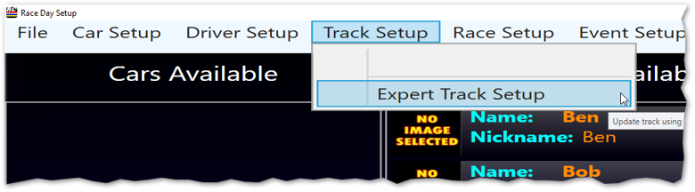
- Launch Race Coordinator, then click the Track Setup menu and select
Expert Track Setup.
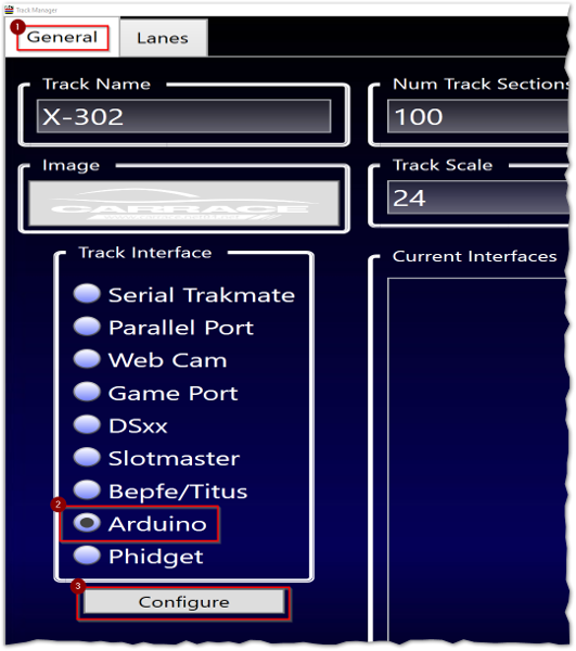
- On the General tab, enter your track name.
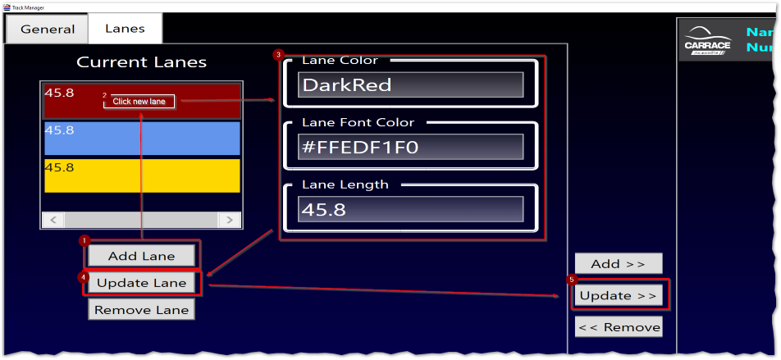
- Switch to the Lanes tab, configure lanes and colours for your track, then click the
Update > > button.
- Switch back to the General tab. Under Track Interface heading, click
Arduino, then click Configure.
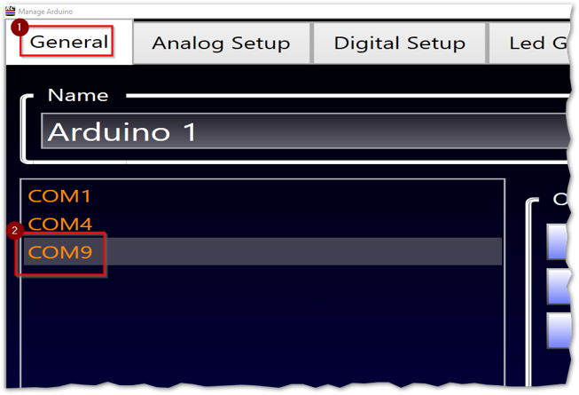
- In the Manage Arduino window on the General tab, select the COM port the
Arduino is connected to, yes it is connected to USB and not a COM port, but this is the way
the Arduino presents itself. The COM port will differ from computer to computer, but is
usually the highest numbered COM port.
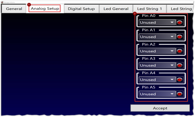
- Switch to the Analog Setup tab, then set all the pins to Unused.
- Switch to the Digital Setup tab and set the following:
Pin 5 (If using Power Cut relays) Relay: L3 Pin 6 (If using Power Cut relays) Relay: L2 Pin 7 (If using Power Cut relays) Relay: L1 Pin 8 Lap L1 Pin 9 Lap L2 Pin 10 Lap L3 Pin 13 Callbutton Remaining Pins Unused 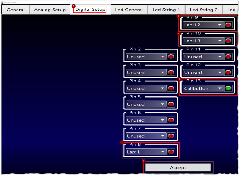
- Click Accept.
- Back on the Track Manager window, click the Update > > button to save your Arduino configuration.